| PEARSON CONSULTING | SOFTWARE | SERVICES | PROJECTS | IDEAS | ABOUT |
A2. Software/Hardware support (USI)
B2. Single Read function
This project provides a minimal I2C Slave that can be used with an Arduino
or other board that can act as an I2C Master.
The four wire interface provides VCC, GND, SCL, and SDA signals. Since VCC is
supplied by the Master board, this design is compatible with 5v and 3.3v
systems provided that the AVR chip supports the voltage level. (2.7v-5.0v) or
(1.8v-5.0v).
The software is designed to run with a Slave using an 8 MHz CPU clock (uncheck
the CKDIV8 fuse when programming). No adjustment is needed to support the
Master provided 100 kHz or 400 kHz SCL clock speeds. However, if a different
CPU clock is used, it must be at least 16 times the SCL clock.
The software is compatible with Atmel Studio 6.2 and is written in 'C'.
Hardware
Components for a basic A2+B2 Slave device to read back data using an ATtiny84A, 85, 2313, or any AVR with a USI hardware section.
 |
 |
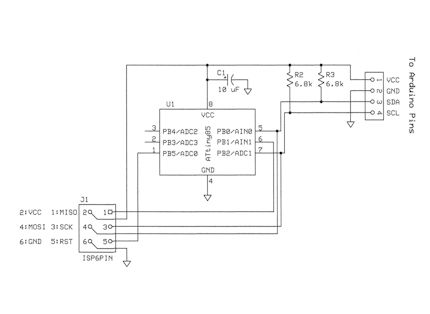
| Schematic A2B2 | Bread Board A2B2 |
Parts List
| 1 | Protoboard |
| 1 | AVR microcontroller (example Atmega85) |
| 1 | 10uF electrolytic capacitor (optional for power filtering) |
| 2 | 6.8k ohm 1/4 watt resistor |
| 4 | Jumper wires for VCC, GND, SCL, and SDA lines. |
| 1 | Arduino UNO |
Software Files
After setting up a bare C project in Atmel Studio, copy these files into the source code area and add them to the project.- usiTwiSlave.c - Interrupt driven driver for I2C Slave with a FIFO data buffer.
- usiTwiSlave.h - Header for driver.
Copy the code from Slave_A2B2.c
into your main.c for the project and build.
Program the AVR chip and connect up the jumper wires to the Arduino board.
The complete Atmel Studio project can also be downloaded from GitHub.
Slave A2B2
Load the Arduino_A2B2_demo code into
the Arduino IDE and select the board and COM port that you will use. Build and
download into the Arduino board.
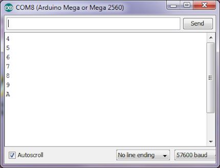
Go to Tools > Serial Terminal to monitor the data being read back.
If the AVR is connected to the Arduino, the terminal window should display an
incrementing data count as shown below.
 |
| Terminal A2B2 |
Process Flow: Like most C programs, the process begins with a call to main()
to start the program.
The first thing that main() does is initialize the data count to 0.
It then calls usiTwiSlaveInit( adrs ) to initialize the USI support software and hardware and pass it
the I2C address of the Slave. The address is a unique 7-bit value and a
different value has to be assigned to each Slave on the I2C bus to prevent
conflicts.
Once the hardware is setup, the interrupts are enabled by calling sei() to set
the Global Interrupt flag.
Finally, the Slave is activated by calling usiTwiSlaveEnable(). After this point,
the Slave will automatically respond to its address. If sent as a SDA_R mode
address, it will copy the data from the TxBuf[] FIFO into the transmit register
to be sent out.
The process now enters an infinite WHILE loop. This simple loop continually
checks for data still in the Transmit FIFO Buffer by calling twiDataInTransmitBuffer()
and checking for a FALSE return value.
When the IF statement evaluates true (i.e. TxBuf[] empty), the data count is
copied into the TxBuf[] FIFO so that it will be sent out on the next read.
The last step is to adjust the count to show that the Slave is modifying the
data.
This is somewhat of a hack to demonstraite the Read process. Normally, a Read will follow a Write operation. The Write command will tell the Slave what to send back and that data will be loaded into the TxBuf[] FIFO. This is the method that will be used in the following A1B3 and A2B3 examples.
If the Serial Monitor does not show data, check wiring and that the Slave address being
sent by the Master is the same as the one the Slave is set to.
If the characters on the Serial Monitor look strange, check that the baud rate setting
(lower right corner) is set to 57600 to match the Arduino Serial.begin(57600) setting.
Unfourtunatly, an oscilloscope is needed to troubleshoot farther than code inspection and
wiring checks.
- The Arduino Master can read data from the AVR Slave at the specified I2C address.
- The data can be modified by the Slave.
- The hardware is wired correctly for I2C communications.