| PEARSON CONSULTING | SOFTWARE | SERVICES | PROJECTS | IDEAS | ABOUT |
A1. Hardware support (TWI)
C1. Multiple Write functions
This project is a step up from the simple command processing of the prior
project. It will include a table structure that allows it to easily handle
multiple types of commands sent from an Arduino or other board that can
act as an I2C Master.
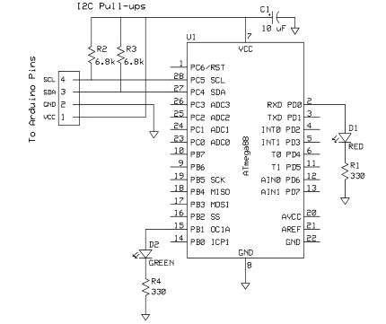
The four wire interface provides VCC, GND, SCL, and SDA signals. Since VCC is
supplied by the Master board, this design is compatible with 5v and 3.3v
systems provided that the AVR chip supports the voltage level. (2.7v-5.0v) or
(1.8v-5.0v).
The software is designed to run with a Slave using an 8 MHz CPU clock (uncheck
the CKDIV8 fuse when programming). No adjustment is needed to support the
Master provided 100 kHz or 400 kHz SCL clock speeds. However, if a different
CPU clock is used, it must be at least 16 times the SCL clock.
The software is compatible with Atmel Studio 6.2 and is written in 'C'.
Hardware
Components for a basic A1+C1 Slave device to receive commands using an ATmega44/88/168/328, ATmega164/324/644/1284, or any AVR with a TWI hardware section.
 |
 |
| Schematic A1C1 | Bread Board A1C1 |
Parts List
| 1 | Protoboard |
| 1 | AVR microcontroller (example Atmega88A) |
| 1 | 10uF electrolytic capacitor (optional for power filtering) |
| 2 | 6.8k ohm 1/4 watt resistor |
| 4 | Jumper wires for VCC, GND, SCL, and SDA lines. |
| 1 | Arduino UNO |
Software Files
After setting up a bare C project in Atmel Studio, copy these files into the source code area and add them to the project.- access.c - Message parser.
- access.h - Message parser header.
- dev_led_1.c - Single LED device control code.
- dev_led_1.h - Single LED device control header.
- dev_led_pwm.c - PWM LED brightness control code.
- dev_led_pwm.h - PWM LED brightness control header.
- flash_table.h - Flash table access subroutines.
- flash_table.s - Flash table access subroutines header.
- function_tables.c - Lookup tables for device functions.
- function_tables.h - Lookup tables header.
- i2c_address.c - Generate I2C address from external jumpers.
- i2c_address.h - Generate I2C address header.
- initialize.h - Device initialization process.
- initialize.h - Device initialization header.
- service.c - Device service process.
- service.h - Device service header.
- sysdefs.h - Common defines and structs.
- sysTimer.c - System timer service.
- sysTimer.h - System timer header.
- twiSlave.c - Interrupt driven driver for I2C Slave with a FIFO data buffer.
- twiSlave.h - Header for driver.
Copy the code from Slave_A1C1.c
into your main.c for the project and build.
Program the AVR chip and connect up the jumper wires to the Arduino board.
The complete Atmel Studio project can also be downloaded from GitHub.
Slave A1C1
Load the Arduino_A1C1_demo
code into the Arduino IDE and select the board and COM port that you will use.
Build and download into the Arduino board.
If the AVR is connected to the Arduino, one LED will blink and one LED will glow
and dim.
Process Flow: In this architecture, each module has three processes:
- Initialization - Sets up any hardware and/or software variables.
- Service - This is called for any periodic operations of the module.
- Access - This section parses and processes any commands for the module.
Now main() only has to call initialize() to have all of the resources to be used initialized and then enter an infinite WHILE loop to continually call the service() and access() support processes.
Initialization: This process does system and device initialization.- Enable the /RST line pull-up resistor.
- Initialize Timer0 to generate the system TIC flags.
- Set up the I2C/TWI interface and Slave Address.
- Initialize the access state variables.
- Walk through the device init functions to set up each devices hardware and state variables.
- Enable Global interrupts.
- Enable the TWI interface to accept messages.
Service: This process supports devices that perform a periodic operation or require periodic updates. It cycles through all of the device service methods giving each a chance to do something. The service methods are self-timed using the 1ms and 10ms TIC flags. There are four of each. The code could be modified to change the ratio, but based on several projects, four seems enough.
Access: The function gathers up incomming I2C bytes into a message.
It checks for data in the Receive FIFO Buffer by calling twiDataInReceiveBuffer().
If data is there, it retrives the byte into a buffer and the checks if the
buffer has overflowed. If it has, then it is an error and it flushes all data from
the I2C input buffer to try to recover.
It then proceeds to check how much data has been received. There are three
conditions to look for:
- The first byte of a message has just been received and the header format is then checked.
- The first three bytes of a message have been received and the device access function table can be retrieved.
- The entire message has been received and is ready to be sent to the selected device for processing using the access function table to find the command's method.
One of the problems with supporting multiple types of commands
is that not all of the commands may be the same length. So, to address this, the
message protocol will add one byte to the command message to include the length.
Since most messages are short (i.e. usually less than 16 bytes), only 4 bit of this
byte will contain the length. The other 4 bits will be the 1's complement of those
4 bits to make a semi-unique byte that can act as a header for the message.
When the module is waiting for a message, it takes the first byte it receives and
XORs the upper and lower nibbles (should result as 0) to see if it is a proper
header. If so, it saves the lower nibble, the one with the length, and collects that
many bytes after receiving the Device ID byte and the Command byte.
The Device ID is another byte added to allow for multiple types of devices to
be within the same Slave module. In this example, there are two. Device 0x20 will
be the single LED and device 0x30 will be a PWM brightness controlled LED.
Each of these will have their own command set. Either can be changed with out
affecting the coding of the other. In addition, more devices can be added without
affecting the existing device code.
Command Format:With this message format, each command message is a
minimum of three bytes long and can have a maximum of 16 data bytes associated
with it.
HDR DEV CMD [Data0] ... [Data15]
where
- HDR - Header byte
- DEV - Device ID byte
- CMD - Command byte
Now that this project is working, it provdes another baseline of operations.
- The Arduino Master can command multiple devices inside the AVR Slave.
- The hardware is wired correctly for I2C communications.